Build & Setup Guide
Building a GELLO Leader Arm for Franka FR3: Hardware Assembly, Wiring, and Pitfalls
An end-to-end account of building and calibrating a GELLO teleoperation arm for a Franka Research 3 — the mechanics, the wiring (including the cables I had to extend myself), the pitfalls that actually cost me time, and the checklist I wish I'd had on day one.
The finished leader arm driving the FR3 in real time — each run recorded as a demonstration for imitation learning.
Scope
This guide focuses on the hardware build: parts, 3D printing, servo installation, wiring, spring setup, and first power-on checks.
It does not fully cover ROS 2 controller setup, Franka FCI configuration, or policy training — I only include the software notes that were necessary to verify the hardware.
01 · Introduction
What this guide is for
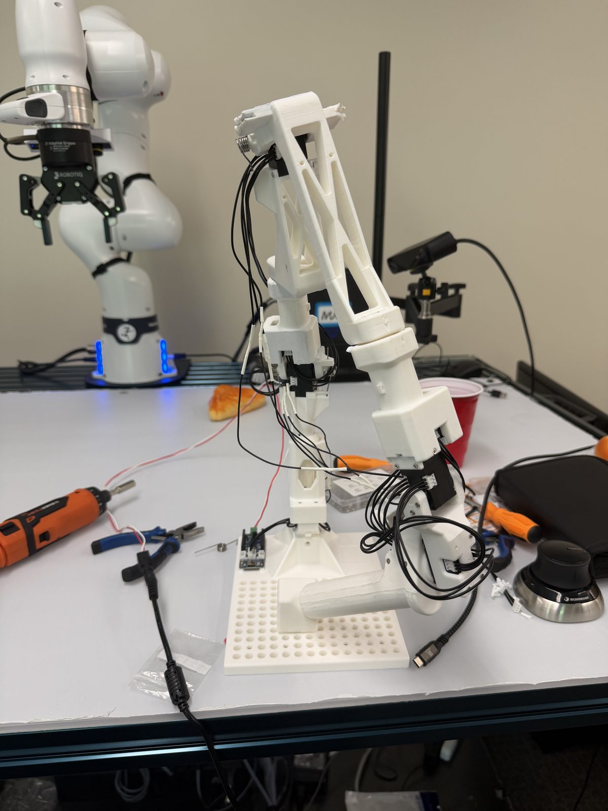
GELLO is a low-cost, 3D-printed leader arm: a passive kinematic twin of the robot that you move by hand while the real arm follows, so you can record smooth, intuitive demonstrations for imitation learning.
This guide documents the exact build I used to teleoperate a Franka FR3 — what to buy, how to assemble and wire it, what went wrong, and how to confirm it works before the robot ever moves.
My hardware setup
- Follower robot: Franka Research 3 (7-DoF), with a Robotiq 2F-85 / Franka Hand gripper.
- Leader: GELLO arm built from the
gello_mechanical/franka_fr3design. - Actuators: 7× DYNAMIXEL XL330-M288-T (joints) + 1× XL330-M077-T (gripper trigger).
- Controller: ROBOTIS OpenRB-150, daisy-chaining the bus to the PC over USB-C.
- Software:
gello_software(driver) + RLinfgello-teleop(FK + agent).
02 · Bill of Materials
What you need to buy and print
Everything I actually used — exact models, quantities, and where I bought them. The seven joint servos are the bulk of the cost; the structural parts were printed in-house.
| Item | Spec / model | Qty | Unit | Source |
|---|---|---|---|---|
| StructuralFR3 GELLO 3D-printed partsPrinted on a Bambu. Tolerances matter — some holes need sanding, drilling, or heat-set tweaks. | 18 pieces · gello_mechanical/franka_fr3 | 18 | in-house | GitHub ↗ |
| ActuatorArm joint motorsMain joint servos. Use the TTL 3-pin version — not the RS-485 4-pin. | DYNAMIXEL XL330-M288-T | 7 | $27.49 | ROBOTIS ↗ |
| Frame / IdlerHinge frame + idler setXL330 hinge/idler side. Keep spares — small plastic parts are easy to lose. | FPX330-H101 (4 pcs) | 1 set | $9.80 | ROBOTIS ↗ |
| ActuatorTrigger / gripper motorGripper trigger input. Needs its own gripper-range calibration in software. | DYNAMIXEL XL330-M077-T | 1 | $27.49 | ROBOTIS ↗ |
| ControllerGELLO controllerMotor cable into a white Dynamixel port; USB-C to the PC. | OpenRB-150 | 1 | $28.64 | ROBOTIS ↗ |
| CableLong Dynamixel cableFor longer joint routing. Must be the 3-pin TTL JST-JST cable. | Robot Cable-X3P JST-JST, 360 mm | 3 | $10.95 | MyBotShop ↗ |
| CableUSB cable for OpenRBMust support data — charge-only cables power the board but hide the serial device. | USB-A → USB-C, ~2 m | 1 | $8.00 | Amazon ↗ |
| PowerExternal DXL power supplyOptional for passive reading; required for torque / damping / virtual-spring mode. Never 12V on XL330. | 5V, ≥3A (5A preferred) | 1 | $12.00 | Amazon ↗ |
| ToolScrewsKeep several lengths — some printed holes are shallow. | M2 & M3 self-tapping | 1 set | $12.00 | Amazon ↗ |
| SpringJoint springs (J2 & J4)Both from one stainless torsion-spring assortment kit (box label 1.2*10*35mm-180°). The kit lets you test-fit stiffnesses. | Torsion, 1.2 × 10 × 35 mm, 180° | 2 | $11.40 / kit | Amazon ↗ |
Roughly $320 in parts (about $335 with the optional 5V supply), beyond the in-house 3D prints.
03 · Mechanical Assembly
Putting the arm together
3D printing
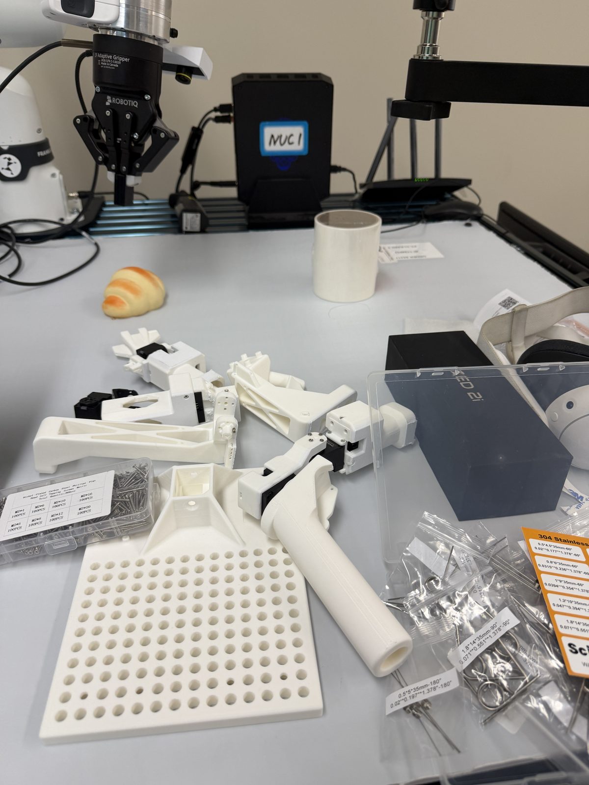
The arm is 18 printed pieces from the franka_fr3 design. It doesn't carry the load a real FR3 does, but the joints still take repeated screw pressure and hand force during teleop — so I printed at ~50% infill, favoring strength over a featherweight part.
- Supports + auto-orient: enable supports and let the slicer auto-orient each part — several are awkwardly shaped, and the default STL orientation often isn't the best one to print.
- Hole compensation: turn it on, or screw holes print slightly undersized — and fighting (or re-drilling) every hole eats a lot of assembly time.
- Use self-tapping screws for almost everything: ordinary machine screws are very hard to drive into printed plastic, while self-tappers cut their own clean thread.
- Motor order: install the servos from the base outward, seating each before adding the next link — and leave their IDs unset for now (assigned one at a time during wiring).
Spring installation
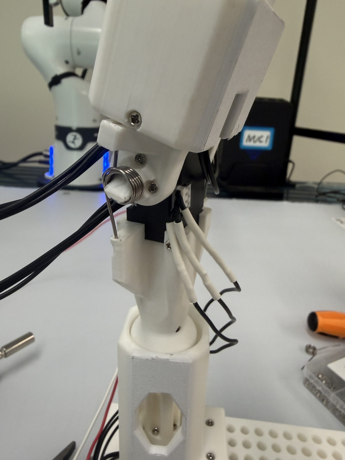
Two torsion springs (the same 1.2 × 10 × 35 mm, 180° size) sit at joints 2 and 4 to offset gravity so the passive arm floats instead of sagging. The mount angle and pretension are the fiddly part: too stiff and the arm fights your hand, too loose and it droops. I set them so the arm holds a neutral pose on its own with almost no effort to move.
Cable routing & base mounting
Route each lead along its link with enough slack to survive the joint's full range — a cable that's taut at one extreme will unseat its connector or cap the motion. Finally, fix the base so the leader can't tip during teleop and its reach maps comfortably onto the robot's workspace.
04 · Wiring
From servos to the PC
The XL330s share a single 3-wire TTL bus: each servo has two ports, so you chain them servo-to-servo from the base out to the gripper. The first servo plugs into the OpenRB-150's white Dynamixel port; the board is the bus master and talks to the PC over a single USB-C cable that carries both power and data.
It enumerates as a USB CDC-ACM serial device — on my machine /dev/ttyACM0(note: ACM, not the FTDI ttyUSB* some docs assume). Confirm it before going further:
ls -l /dev/serial/by-id/      # stable name for the OpenRB-150
ls -l /dev/ttyACM0            # what gello_software expects
Set each servo's ID before you chain them
This is the step that bites everyone: every Dynamixel ships with the same factory ID (1). Put them all on one bus and they answer at once and collide, so a scan flickers between seeing one device and none. Before building the daisy-chain, connect one motor at a time and use ROBOTIS's software (Dynamixel Wizard 2.0, through the OpenRB-150) to write a unique ID to each — 1→7 for the joints from base to tip, and 8 for the gripper. Only one servo may be on the bus while you write, or the new ID gets broadcast to every ID-1 servo at once.
The cables were too short
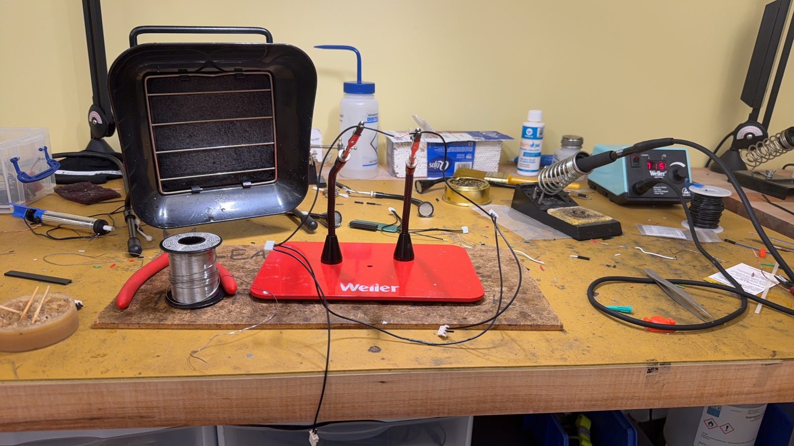
The stock Dynamixel leads didn't reach across the longer links of this build, so I made my own: cut to length, soldered, and heat-shrunk each joint's extension. It's tedious but worth doing carefully — a cold joint here turns into the kind of intermittent bus fault that's miserable to chase later.
When external 5V is needed
For passive teleoperation — how GELLO is used here, with servo torque off — the OpenRB-150's USB-C power is enough; the arm only reads joint angles. An external supply (5V, ≥3A — 5A preferred, never 12V on XL330) only matters if you actually drive the servos: torque, damping, or virtual-spring mode. I first thought it was required and it wasn't — a misread of a torque-enable warning.
05 · Common Hardware Pitfalls
What actually cost me time
Eight servos, one ID
Dynamixel servos ship with the same factory ID (1). Leave them unassigned and all eight answer at once and collide — scans see one device or none. Assign IDs 1–8 with only one servo on the bus at a time. Looks like a power fault; isn't.
Wrong Dynamixel cable type
XL330s use a specific JST connector/pitch. A lead from another Dynamixel family may fit but mis-seat — keep the cable matched to the servo.
Printed holes too tight
3D-printed seats and bores come out undersized. Ream to spec rather than forcing parts — over-pressing cracks mounts and binds joints.
Spring too stiff / wrong angle
An over-tensioned or badly-anchored gravity spring makes the arm fight you or droop. Tune pretension and mount angle so it floats neutrally.
Cable too short
A lead that's taut at a joint extreme pops its connector or caps the range of motion. This is exactly why I ended up soldering extensions.
GELLO ↔ FR3 pose mismatch
Calibration assumes leader and follower start matched. If they disagree at startup, every command is offset — always align GELLO to the robot's home before enabling control.
06 · First Power-On Checklist
Confirm it works before the robot moves
- ✓Board power LED on after USB-C connect.
- ✓Device appears under
/dev/serial/by-id(and as/dev/ttyACM0). - ✓All 8 motors detected on a bus scan (IDs 1–7 joints, 8 gripper) at 57600 baud.
- ✓Joint signs correct — validated by end-effector tracking, not single-joint motion (§7).
- ✓Joint offsets calibrated against a known reference pose.
Reference: my calibrated config
After ID assignment and calibration, the per-port config GELLO reads from looked like this — the offsets and signs are build-specific, so yours will differ:
# gello_agent.py  PORT_CONFIG_MAP entry
"/dev/ttyACM0": DynamixelRobotConfig(
    joint_ids     = (1, 2, 3, 4, 5, 6, 7),
    joint_offsets = (3.142, 6.283, 6.283, 1.571, 9.425, 4.712, 3.142),
    joint_signs   = (1, 1, 1, -1, 1, -1, 1),
    gripper_config= (8, 184, 142),   # (id, open, close)
)
07 · Notes for FR3 Teleoperation
How it behaves once it's live
Passive GELLO has no force feedback
The leader's motors are torque-off; it senses your motion and never pushes back. You feel the spring and the arm's own inertia — nothing from the robot or its contacts — so move deliberately, especially near objects.
The FR3 syncs to the GELLO pose, not its joints
One subtlety reframes all the calibration: RLinf's GELLO path is not a joint-to-joint leader/follower. It runs forward kinematics on GELLO's joints to get an end-effector pose, takes the Cartesian delta against the robot's current tool pose, and lets inverse kinematics redistribute it across the real joints.
GELLO joints ──(offset, sign)──▶ joint angles
        └─▶ FrankaFK ─▶ end-effector pose
              └─▶ Cartesian delta vs current TCP
                    └─▶ IK ─▶ robot joint commands
So moving one GELLO joint does not move the matching robot joint — the robot tracks the end-effector, and IK can hide a wrong joint sign entirely. Validate with whole-arm EE tracking instead. It also means the action space is an EE delta — the same space the policy I was evaluating (π₀.₅-DROID) uses, so leader, dataset, and model all agree.
Always align before enabling the controller
Before each session, pose GELLO to match the robot's home, then enable teleop. Enabling with a large mismatch commands a big instantaneous EE jump — align first, every time.
08 · Teleoperation in action
Driving the FR3 to collect demonstrations
With the leader calibrated, a human drives GELLO and the FR3 mirrors the motion in real time — the rollout clips at the top of this page, each run recorded as a demonstration. Collection runs through RLinf's real-world environment with a Polymetis controller backend.
How the data-collection pipeline is wired — RLinf's real-world env, the Polymetis controller backend, and the LeRobot dataset it produces — is documented on the FR3 cell page →